Katana blog Articles, product updates, and company news


Get inventory trends, news, and tips every month
Explore all categories
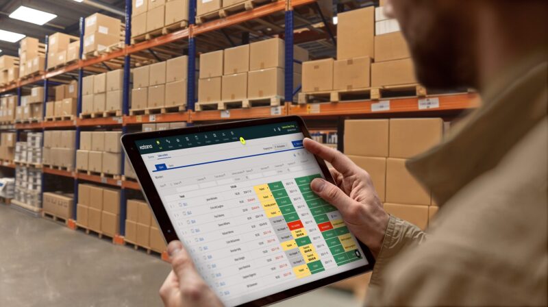
Get visibility over your sales and stock
Wave goodbye to uncertainty with Katana Cloud Inventory — AI-powered for total inventory control
